研究テーマ / Research topic
位置推定補助用UAV群を用いたUAV位置推定システムの実現
Realization of localization system by multiple UAVs
位置推定補助用UAV群を用いたUAV位置推定システムの実現

研究背景
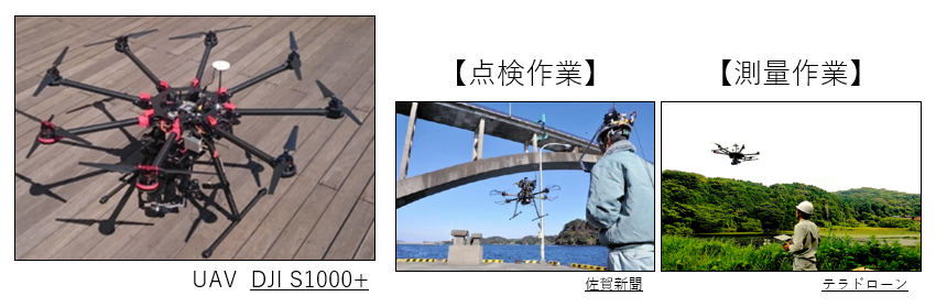
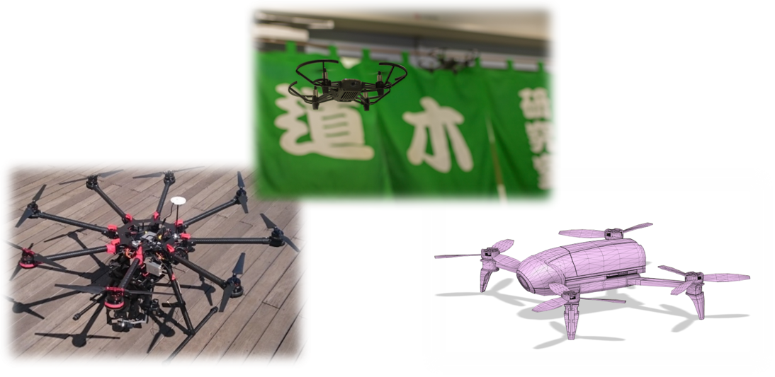
UAV(Unmanned Aerial Vehicle)の飛行性能はここ数年の間で飛躍的な進化を遂げている。当初は個人の趣味嗜好レベルでのホビー用のUAVが一般的であった。その後、産業用UAVとして農業・空撮・点検・測量作業といった分野にまでその適用範囲が拡大している。
現在の産業用UAVの運用方法としては、作業員による操縦が一般的である。しかし、作業員の操縦による運用では作業成否が操縦スキルに依存してしまう。そこで、UAVによる作業タスク実行に対する更なる要望としてUAVの自律飛行による作業タスクの効率化が挙げられる。
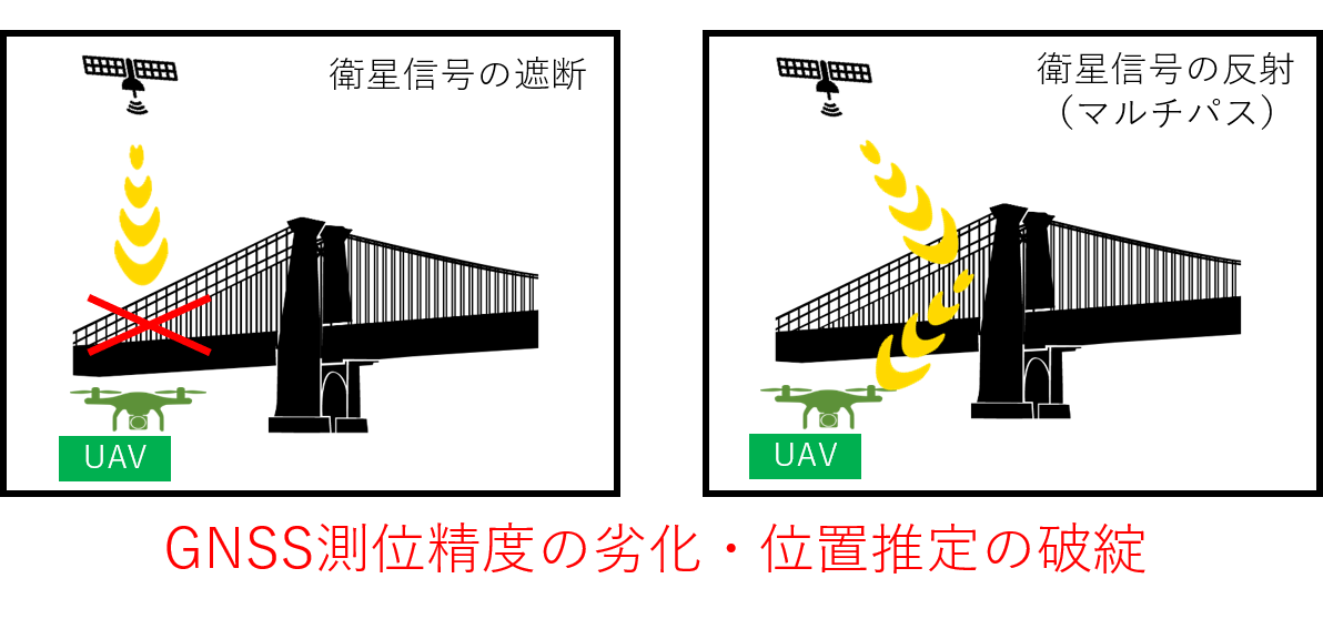
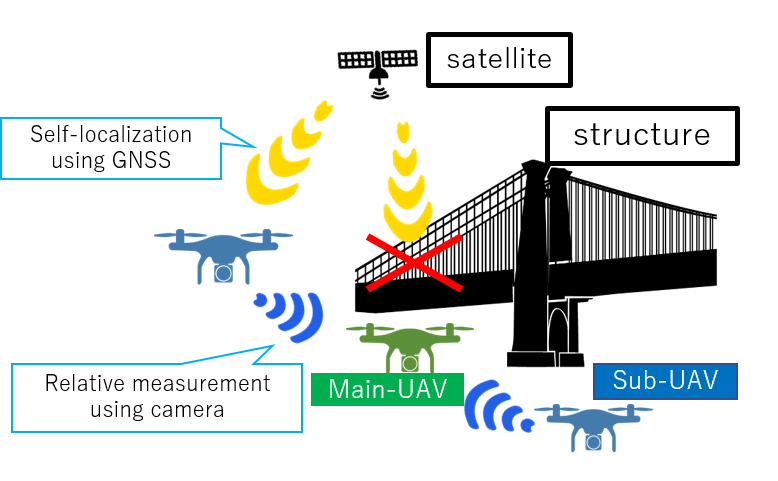
UAVの自律飛行による作業タスクの効率化を行う上で重要となるのがUAVの自己位置推定である。UAVの自己位置推定には一般的にGNSS(全球測位衛星システム)が用いられる。GNSSは上空が開けた環境で有効に機能する特徴を持つ。一方、構造物付近では正確な位置推定が困難であるという特徴も持つ。点検等の作業タスクを想定したとき、UAVは構造物付近を必ず飛行する。その為、UAVの自律飛行による作業タスク実行を行う上で構造物付近の位置推定が課題となる。
研究紹介
名古屋大学内にあるモデル橋(N2U-BRIDGE)において、実際に主機・補機となるUAVを飛行させ、理想的な状態で提案システムが正常に機能するかどうかの原理検証を行った。
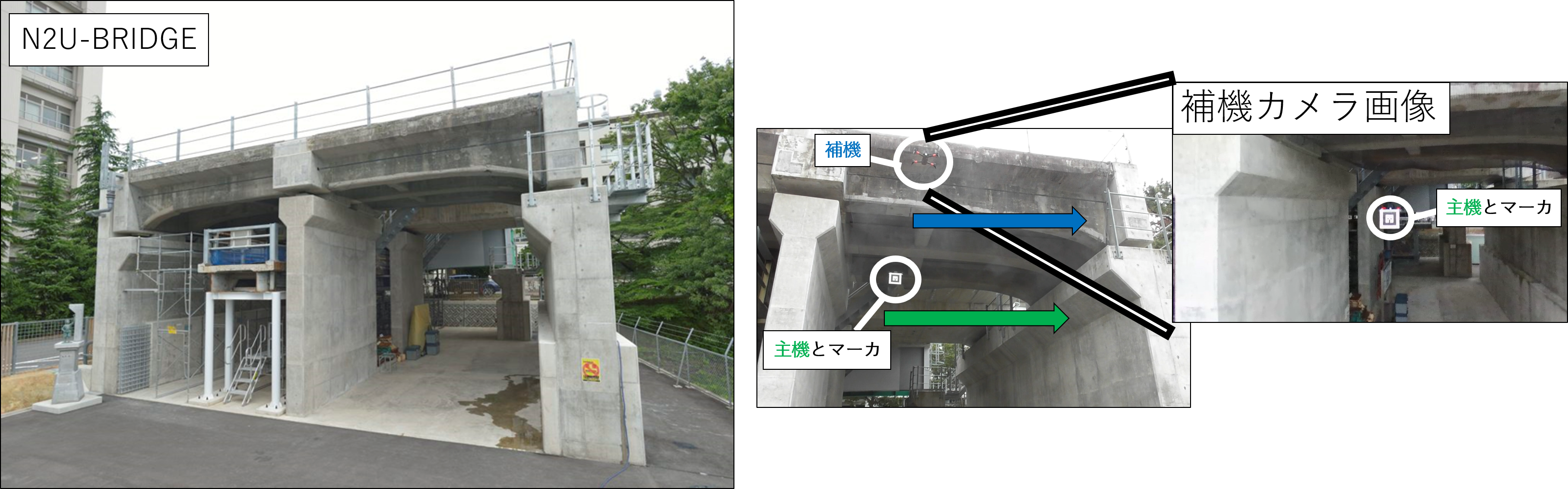
実験では、主機はGNSS信号が受信不可である領域を飛行し、補機はGNSS信号が受信可能な位置から主機位置の推定を行う。この時、主機・補機の位置関係が一定となるように制御を行い、相対位置関係を理想化させた。
結果として、主機単体での自己位置推定(GNSSのみ)では、数十mオーダの誤差が発生し、補機を用いた位置推定(GNSS+カメラ)では数mオーダの誤差となった。この時、補機を用いた位置推定ではGNSS誤差が数mオーダと支配的となっており、相対位置計測誤差は十数cmオーダであった。GNSS誤差に関しては、RTK-GNSSに代表される先行技術の導入により数cmオーダの誤差まで軽減可能であることが知られている。その為、実験において、本システムでは全体として十数cmオーダの精度での位置推定が可能だと判明した。
提案システムにおける位置推定原理を説明する。提案システムでは、2段階による主機・補機位置推定を行う。
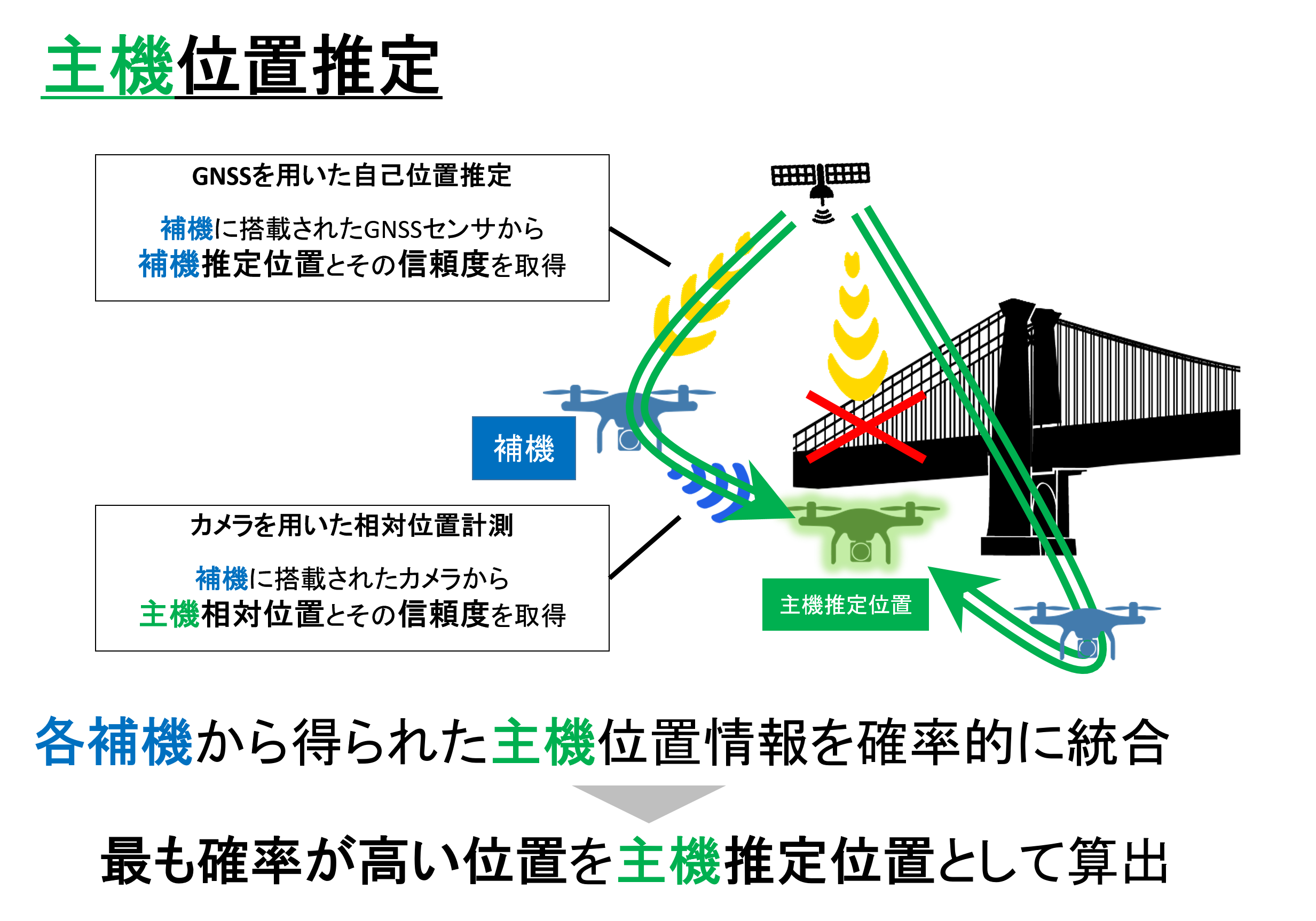
1段階目として、全補機群情報から一意な主機推定位置を算出する。補機群は自身に搭載されたGNSS・カメラセンサにより、主機の位置情報に関する情報を得る。GNSSセンサからは自身の補機推定位置とその情報信頼度を、カメラセンサからは主機相対位置とその情報信頼度が得られる。本システムでは、各補機から得られた主機位置情報を確率的に統合を行った後に、最も確率が高い位置を主機推定位置として算出する。
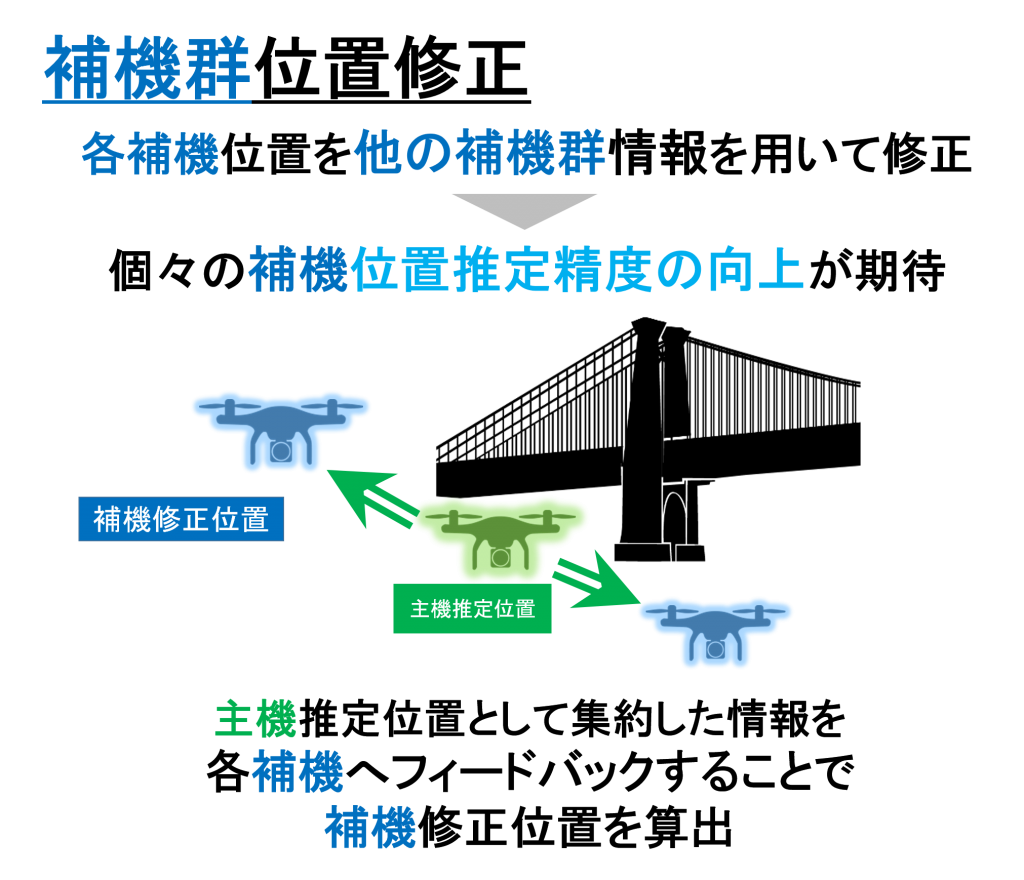
2段階目として、1段階目で算出した主機推定位置を用いて、補機群の位置修正を行う。補機は既にGNSSにより自身の位置情報を把握しているが、他の補機情報を用いて位置を修正することで個々の補機位置推定精度が向上すると期待できる。すなわち、主機推定位置として集約した情報を各補機へフィードバックすることで補機修正位置の算出する。
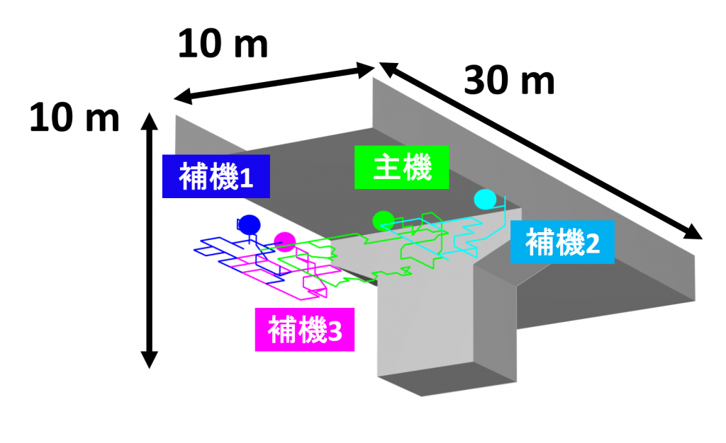
シミュレーションを用いて提案システムの有効性を検証する。図に示す10 m × 10 m × 30 mの構造物の一部分を主機1機(位置推定不可)、及び補機3機で点検すると想定する。主機・補機群の点検経路は先行研究(木村 圭佑. 他、計測自動制御学会論文集、2020)を用いて算出した。この時の各機体のGNSS自己位置推定誤差と提案システムによる主機・補機群位置推定結果を比較する。
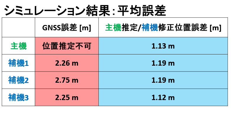
結果として、シミュレーションにおける平均誤差を算出したところ上図のようになった。主機は構造物の影響により位置推定不可であったのに対して約1.1 m程度で位置推定が可能になった。また、補機群は約2.2~2.7 mのGNSS誤差に対して提案法による位置修正を行うことで、約1.1 m程度にまで誤差が改善した。
関連研究
Japanese Ver.
Realization of the localization system by multiple UAVs
Research background
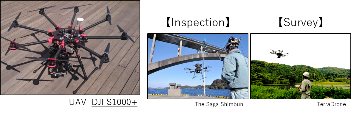
The flight performance of the Unmanned Aerial Vehicle (UAV) has evolved dramatically in recent years. Initially, UAVs for hobby at the level of personal taste preference were common. Since then, the scope of application has expanded to fields such as agriculture, aerial photography, inspection and survey work as industrial UAV.
As a current method of operating an industrial UAV, a maneuver by a worker is common. However, in the operation by the operation of the worker, the success or failure of the work depends on the control skill. Therefore, as a further request for the execution of task tasks by the UAV, the efficiency of task tasks by an autonomous flight of the UAV can be mentioned.
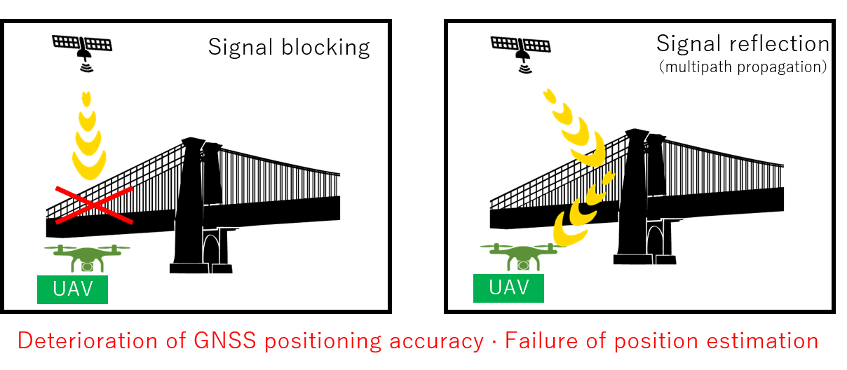
It is self-localization of UAV that is important to the efficiency of task tasks by an autonomous flight of the UAV. GNSS (Global Navigation Satellite System) is generally used for self-localization of UAV. GNSS has features that work well in open environments. On the other hand, there is also a feature that accurate position estimation is difficult near the structure. The UAV always flies near the structure when assuming a task such as inspection. Therefore, position estimation in the vicinity of the structure becomes an issue when performing work tasks by UAV autonomous flight.
Research
The proposed system has been studied only on simulations. Therefore, we have verified the principle of the proposed system to work properly under an ideal environment. UAVs were actually flown as Main-UAV and Sub-UAV, at the model bridge(N2U-BRIDGE) in Nagoya University.
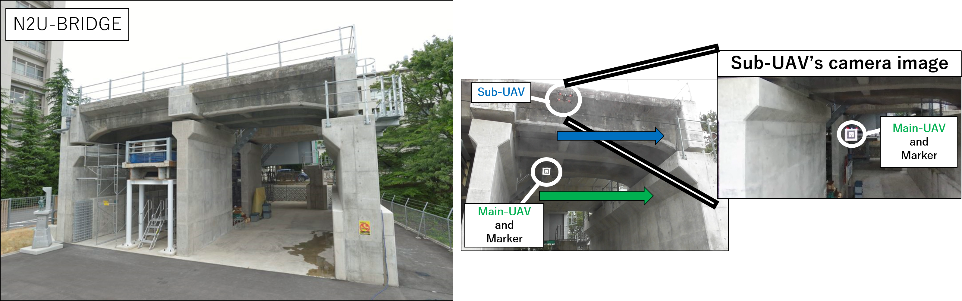
In the experiment, Main-UAV flies in the area where the GNSS signal cannot be received, and Sub-UAV estimates Main-UAV position from the position where the GNSS signal can be received. At this time, we controlled the position relationship between Main-UAV and Sub-UAV to be constant and idealized the relative position relationship.
As a result, the GNSS error of Main-UAV (GNSS only) was several tens of [m], and the estimation error of Main-UAV from Sub-UAV(GNSS + camera)was several of [m]. At this time, in the estimation of Main-UAV from Sub-UAV(GNSS + camera), the GNSS error was dominant on the order of several [m], and the relative position measurement error was on the order of tens of [cm]. Regarding the GNSS error, it is known that the error can be reduced to the order of several [cm] by introducing the prior art represented by the RTK-GNSS. Therefore, in experiments, it was found that this system can estimate the position with an accuracy of the order of tens of [cm] as a whole.
In the future, in order to further verify the proposed system, an actual machine experiment on an actual bridge is planned.
We describe the principle of position estimation in the proposed system. In the proposed system, Main-UAV and Sub-UAVs localization is performed in two stages.
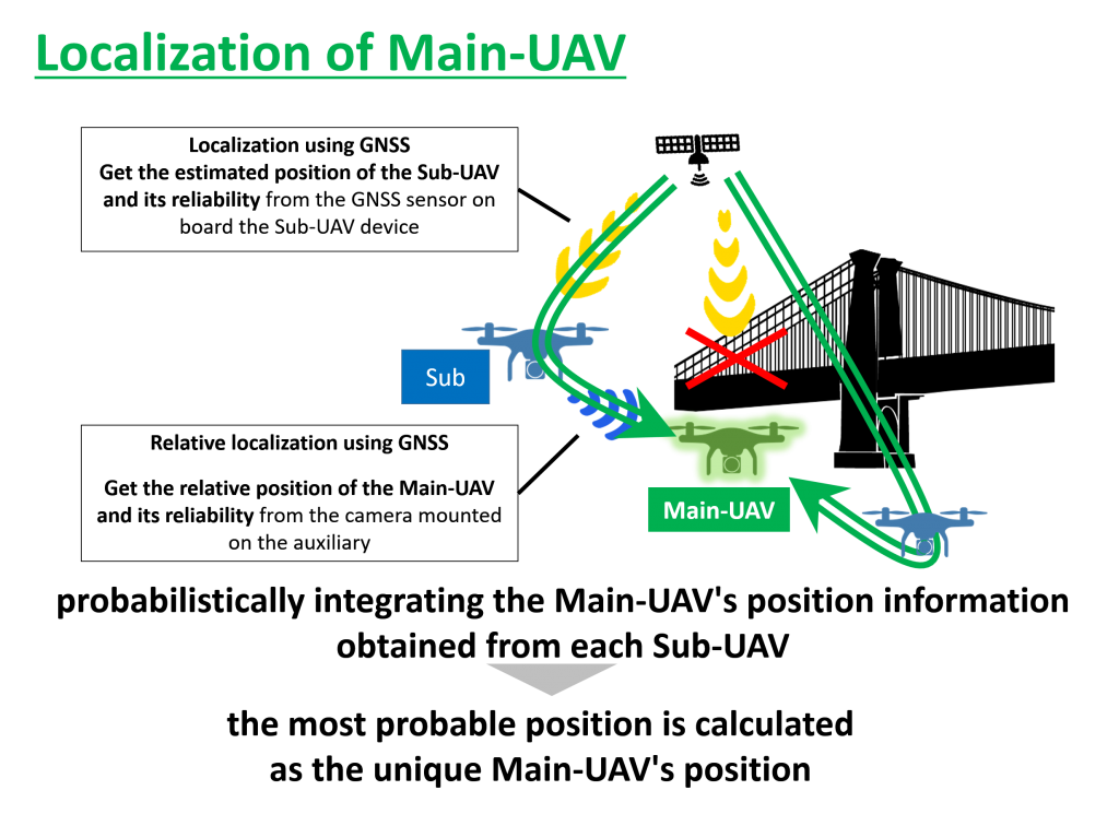
In the first step, a unique Main-UAV’s position is calculated from the total Sub-UAV’s information. The Sub-UAV obtain information about the Main-UAV’s position information from their onboard GNSS and camera sensors: the estimated position of the Sub-UAV and its information reliability from the GNSS sensors and the relative position of the Main-UAV and its information reliability from the camera sensors. In this system, after probabilistically integrating the Main-UAV’s position information obtained from each Sub-UAV, the most probable position is calculated as the unique Main-UAV’s position.
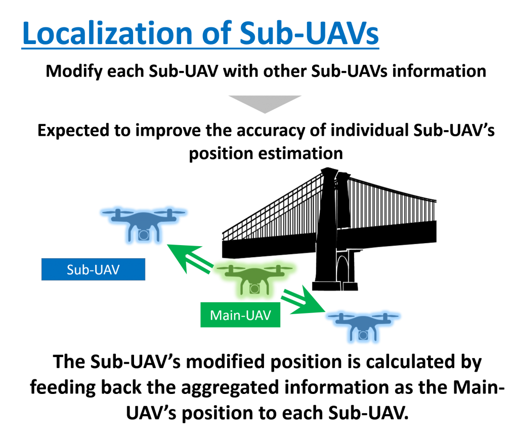
In the second step, the position of the group of Sub-UAV is modified by using the estimated Main-UAV’s positions calculated in the first step. Although each Sub-UAV already knows its own position information by GNSS, we expect that the accuracy of each Sub-UAV’s position estimation will be improved by modifying its position using other Sub-UAV’s information. In other words, the information aggregated as the Main-UAV’a position is fed back to each Sub-UAV to calculate the Sub-UAV’s modified position.
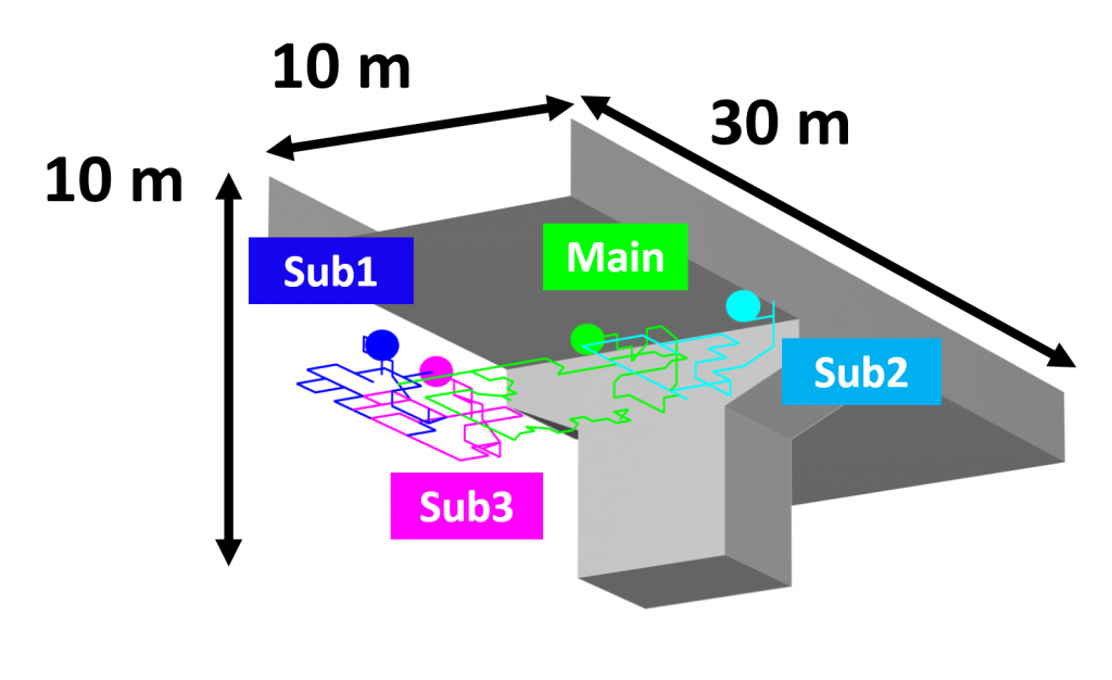
Simulation is used to verify the effectiveness of the proposed system. It is assumed that a part of the 10 m × 10 m × 30 m structure shown in the figure is inspected by one Main-UAV (localization is not possible) and three Sub-UAVs. The inspection path of the Main-UAV and Sub-UAVs is based on a previous study (Kimura, K. et al., The Society of Instrument and Control Engineers, 2020). We compare the GNSS self-positioning errors of each UAV with the results of the Main-UAV and Sub-UAVs position estimation by the proposed system.
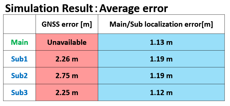
As a result, the average error in the simulation is calculated as shown in the above figure. The positional estimation of the Main-UAV is now possible within about 1.1 m, whereas the positional estimation of the Main-UAV had been impossible due to the structure. For the Sub-UAVs, the positional error of about 2.2-2.7 m was modified to about 1.1 m with the proposed method.
Related research